How to integrate flow control skids into existing pipelines? This question becomes practical when an operating facility needs better flow regulation without replacing an entire pipeline. A flow control skid combines valves, meters, strainers, transmitters, and supporting pipework in one controlled assembly. Its compact layout can improve access and reduce installation time. However, the skid must match the pipeline’s process conditions, connection points, and operating limits.
Successful integration starts with accurate field information. Engineers should verify pipe diameter, material, pressure rating, flow direction, available space, and support locations. A clean drawing is not enough. Existing lines may have unexpected corrosion, vibration, or alignment errors. These details can affect flange connections and skid stability. Isolation points, bypass arrangements, drainage, venting, and safe maintenance access also require careful review. Small omissions often create expensive commissioning delays.
The work should follow a documented design and inspection process. Experienced engineers typically review process data, perform hydraulic checks, confirm instrument compatibility, and examine pressure-relief requirements. They also coordinate welding, non-destructive examination, flushing, pressure testing, and control-system checks with qualified personnel. During commissioning, operators should test valves gradually and compare instrument readings with calibrated references. Real systems rarely behave exactly like the model. That is worth acknowledging. Conditions may change after startup, so monitoring and adjustment should continue. This guide explains the main planning, design, installation, and commissioning decisions needed for a reliable pipeline tie-in.
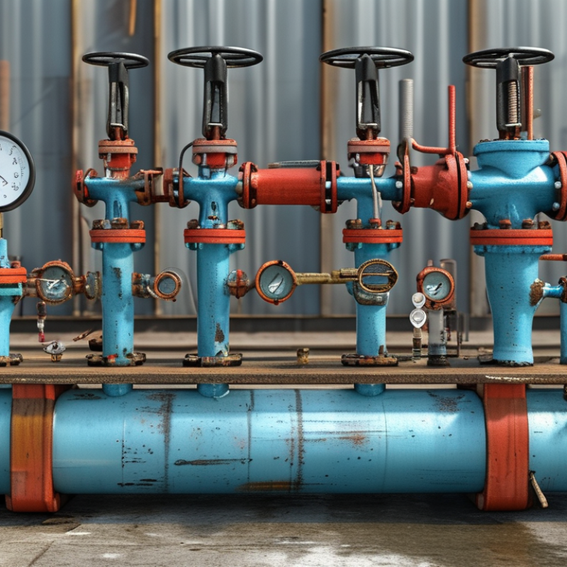
How to Integrate Flow Control Skids Into Existing Pipelines?
Assess Pipeline Conditions and Define Flow Control Requirements
A successful skid integration begins with the existing pipeline, not the new equipment. Review pipe diameter, material, wall thickness, operating pressure, temperature, and fluid properties. Check the latest drawings against the physical line. They often differ.
Inspect supports, flanges, valves, drains, vents, and nearby equipment. Look for corrosion, vibration marks, leaking gaskets, and limited maintenance access. A clean pipe exterior does not prove internal integrity. Non-destructive testing may be necessary before connection work begins.
Define the required flow range, pressure drop, control accuracy, shutdown response, and normal operating conditions. Include startup, shutdown, cleaning, and emergency scenarios. The skid must perform during changing conditions, not only at the design point. Confirm instrument locations, signal types, power requirements, and control-system compatibility with qualified engineers. Applicable codes and site procedures should guide every modification.
Tips
Measure twice in the field. Record flange orientation, bolt-hole alignment, elevation, and available removal space. Leave room for calibration and valve servicing. Review the relief path carefully; a blocked section can create dangerous pressure. I once saw a layout pass a drawing review but fail during installation because a handwheel hit a structural brace. Small details matter. Do not assume old isolation valves will operate smoothly. Test them, document their condition, and replace weak components when justified. Get an independent review when process data is incomplete or conflicting.
Assess pipeline conditions and define flow control requirements before selecting valves, meters, pumps, and skid operating limits.
The assessment compares the existing operating flow with the required control range and the available pipeline capacity. The proposed skid should maintain stable control from approximately 45 to 105 m³/h while operating within the measured pressure range of 6.2 to 8.1 bar. Final equipment sizing should be verified against current wall thickness, pressure ratings, fluid properties, transient conditions, and applicable piping standards.
Integrating a flow control skid into an existing pipeline starts with compatibility, not equipment selection.
Confirm the pipeline’s nominal diameter, schedule, flange rating, design pressure, temperature, and fluid composition. A skid that fits physically may still create excessive pressure loss or unsafe loads.
ASME B31.3 provides process-piping design requirements, while ASME B16.5 defines flange dimensions and pressure classes.
Use both during the interface review. Match the skid’s control valve capacity to actual flow conditions, not only the line size.
The International Energy Agency’s World Energy Outlook 2024 highlights continuing pressure on operators to improve efficiency and reduce losses.
That makes accurate flow measurement important. Yet, field data is rarely perfect.
Recheck old drawings against pipe supports, welds, and corrosion found during inspection.
Tips:
Build a compatibility matrix before fabrication. Include line size, flange class, valve Cv, actuator torque, pressure drop, material grade, and instrument signals.
Verify relief protection and drainage points. PHMSA’s Pipeline Incident 20-Year Trends data shows that corrosion, equipment failure, and incorrect operations remain recurring pipeline incident categories.
Therefore, inspect nearby pipe sections before tying in the skid. A short spool may need reinforcement. Temporary supports may also be necessary during installation.
Small mismatches become expensive later. Allow space for valve removal, calibration, and safe access.
A compact layout is not always the best layout.
Selecting the skid location affects safety, maintenance, inspection, and long-term operating stability. Measure the available area before moving equipment. Leave clear space around valves, instruments, and removable filter sections. Operators should reach every isolation point without climbing over nearby pipework. Keep the skid away from standing water, excessive heat, and uncontrolled vehicle traffic. A level foundation is essential. Small alignment errors can create large pipe stresses.
I have seen installations fail because the layout ignored maintenance access. The skid fitted perfectly, but technicians could not remove a valve actuator. That mistake required costly rework. Check the flow direction, nozzle elevations, and support loads against approved drawings. Confirm the pipeline pressure rating matches every skid connection. Use flexible connections only when engineers verify their movement limits. They are not a cure for poor alignment.
Prepare inlet, outlet, bypass, drain, and vent connections before installation. Confirm flange sizes, gasket materials, bolt grades, and face standards. Provide temporary supports during fit-up, then install permanent supports after alignment checks. Instrument cables need protected routes and enough slack for testing. Pressure testing should follow the project procedure, with sensitive instruments isolated when necessary. Record measurements, photographs, and unresolved deviations. Some field conditions will differ from drawings. Review them honestly before tightening the final bolts.
How to Integrate Flow Control Skids Into Existing Pipelines?
Install, Align, and Connect the Flow Control Skid
Installing a flow control skid begins with field verification, not transport. Confirm pipe size, flange rating, elevation, flow direction, and maintenance clearance. A laser level can reveal small elevation errors before they become costly piping stress. The skid should sit on a rigid, grouted foundation with accessible anchor bolts. Keep temporary shipping supports until the frame is secured. Do not force flanges into alignment. That shortcut can damage gaskets, instruments, and upstream piping.
Alignment needs both measurement and patience. Check nozzle parallelism, centerlines, bolt-hole position, and pipe strain after tightening. ASME B31.3 requires attention to flexibility, pressure design, and support conditions for process piping. The NACE IMPACT study estimated global corrosion costs near 2.5 trillion dollars annually, or about 3.4% of global GDP. Good installation cannot remove corrosion, but correct drainage, coating inspection, and material selection can reduce avoidable exposure.
Connection work should follow a controlled sequence. Clean flange faces, install compatible gaskets, and tighten bolts in a documented cross-pattern. Instrument tubing must avoid sharp bends and unsupported weight. Leak testing should match the approved procedure, pressure rating, and local requirements. The International Energy Agency estimated fossil-fuel operations released about 120 million tonnes of methane in 2023. That figure makes small sealing errors worth treating seriously. I would not trust a drawing alone. Field conditions often disagree. Recheck everything.
| Integration Stage | Key Activity | Required Data or Dimension | Typical Acceptance Requirement | Recommended Records |
|---|---|---|---|---|
| 1. Existing-Pipeline Survey | Verify the physical route, tie-in points, pipe supports, access space, and existing equipment condition before delivery. | Pipe outside diameter, nominal size, wall thickness, centerline elevation, flange rating, orientation, available maintenance clearance. | Field measurements agree with approved drawings; no unverified dimensions are used for fabrication or installation. | Marked-up piping layout, field survey sheet, photographs, tie-in register. |
| 2. Process and Design Review | Confirm that the skid is suitable for the process service and the existing pipeline operating envelope. | Design flow rate, operating pressure, design pressure, operating temperature, fluid composition, allowable pressure drop, flow direction. | Skid design conditions meet or exceed the applicable pipeline and process requirements. | Approved process datasheet, line list, piping and instrumentation diagram, equipment data sheet. |
| 3. Isolation and Safety Preparation | Isolate, depressurize, drain, purge, and verify the existing pipeline before cutting or opening any connection. | Isolation boundary, lockout points, residual pressure, fluid hazards, purge medium, gas-test requirements. | Zero energy is verified at the work location, and the permit and isolation procedures are approved. | Isolation certificate, permit-to-work, gas-test log, toolbox-talk record. |
| 4. Foundation and Support Preparation | Inspect the foundation, install or verify anchor locations, and confirm that the structure can support operating and test loads. | Skid operating weight, test weight, anchor-bolt layout, foundation elevation, allowable support loads, grout thickness. | Foundation is level and structurally adequate; anchor locations match the skid baseplate pattern. | Foundation inspection report, anchor-bolt survey, structural calculation, leveling record. |
| 5. Skid Installation | Lift, position, and secure the skid using an approved lifting plan and suitable lifting points. | Lifting weight, center of gravity, lifting-point capacity, crane or hoist capacity, access route, weather limits. | Skid is placed without impact damage, distortion, or unauthorized lifting from process piping or instruments. | Lifting plan, equipment inspection certificates, installation checklist, damage inspection report. |
| 6. Leveling and Alignment | Level the skid, align the inlet and outlet connections, and prevent external loads from being transferred to the skid nozzles. | Baseplate level, nozzle elevation, flange face position, pipe centerline, allowable nozzle loads, thermal movement. | Alignment is within the approved project tolerances; connected piping fits without forced alignment. | Alignment report, level readings, flange-gap record, nozzle-load assessment. |
| 7. Mechanical Piping Connection | Connect inlet, outlet, bypass, drain, vent, and relief-system piping according to the approved layout. | Pipe size and schedule, flange standard, gasket type, bolt material, valve orientation, drain and vent locations. | Correct components are installed in the correct flow direction, and all temporary supports are removed only after permanent supports are complete. | Piping inspection report, material certificates, flange-management record, weld map. |
| 8. Welding and Flanged-Joint Control | Complete welds and flange assembly using qualified procedures and controlled tightening practices. | Welding procedure, welder qualification, non-destructive examination extent, bolt torque or tensioning method. | Weld examination and joint inspection meet the governing code and approved inspection plan. | Weld records, examination reports, bolt-tightening report, joint checklist. |
| 9. Instrument and Electrical Connections | Connect pressure, temperature, flow, valve-actuation, control, grounding, and power systems. | Instrument ranges, signal type, power supply, cable specification, hazardous-area classification, grounding resistance requirement. | Loop checks, polarity checks, calibration, continuity, and grounding tests are complete before energization. | Instrument calibration certificates, cable test reports, loop-check sheets, termination schedule. |
| 10. Pressure and Leak Testing | Test the newly connected pressure boundary and verify that valves, flanges, welds, drains, and vents are leak-free. | Test medium, test pressure, test duration, test boundary, pressure-recording method, relief precautions. | No visible leakage or unacceptable pressure loss; test limits follow the approved procedure and applicable code. | Pressure-test certificate, calibrated gauge record, punch-list closure, leak inspection report. |
| 11. Flushing and Cleanliness Verification | Remove construction debris, welding residue, moisture, and other contaminants from the connected piping. | Flushing medium, flow velocity, filtration level, cleanliness criterion, temporary-strainer arrangement. | Discharge quality meets the project cleanliness requirement, and temporary items are removed or documented. | Flushing record, filter inspection log, cleanliness certificate, reinstatement checklist. |
| 12. Functional and Control Testing | Verify valve stroke, control response, alarm functions, interlocks, shutdown actions, and fail-safe positions. | Set points, operating sequence, valve travel, response time, alarm limits, interlock logic, fail position. | All functions operate according to the approved cause-and-effect matrix and control narrative. | Functional-test procedure, cause-and-effect test sheet, alarm and trip report. |
| 13. Commissioning and Start-Up | Introduce the process gradually, monitor operating parameters, and confirm stable flow-control performance. | Start-up sequence, ramp rate, pressure and temperature limits, vibration checks, control-valve position, flow stability. | The skid reaches the required operating condition without abnormal leakage, vibration, pressure fluctuation, or instrument alarms. | Start-up log, operating trend data, commissioning certificate, outstanding-punch-list record. |
| 14. Handover and Maintenance Readiness | Complete documentation, operator training, spare-parts identification, and maintenance-access verification. | As-built drawings, equipment tags, maintenance intervals, isolation points, spare parts, operating limits. | All safety-critical documents are complete, equipment tags are installed, and operators can safely isolate and maintain the skid. | Turnover dossier, as-built P&ID, operation and maintenance manual, training attendance record. |
Integrating a flow control skid into an existing pipeline demands disciplined testing before production service. Confirm the piping alignment, flange condition, valve orientation, and support points. The skid should sit level, with enough clearance for inspection and maintenance. Verify instrument ranges against the pipeline’s actual pressure, temperature, and flow conditions. Small mismatches can distort control performance.
Commissioning should proceed with a controlled pressure test and a documented leak inspection. Check every connection, drain, vent, and impulse line. Stroke each control valve through its operating range, then compare the indicated position with the physical movement. Calibrate transmitters using traceable reference equipment. Record readings at zero flow, low flow, and normal flow. Some signals may drift after startup. That is normal, but unexplained drift needs investigation. Never treat a stable screen value as proof of accurate measurement.
During the first operating hours, monitor upstream and downstream pressure, flow rate, valve position, vibration, and temperature. Set alarm limits from tested operating data, not guesswork. Trend the readings at regular intervals. A sudden pressure drop may indicate a blocked strainer, leaking valve, or faulty impulse connection. Field technicians should compare digital values with local gauges. One detail is easy to miss: cable shielding and grounding can affect signal stability. In practice, commissioning records are not always complete. A second review often finds missing calibration data or an unverified alarm. That review is worth the time.
Confirm nominal pipe diameter, schedule, flange rating, design pressure, temperature, and fluid composition. Physical fit alone is insufficient. Small mismatches hurt.
It lists line size, flange class, valve capacity, actuator torque, pressure drop, materials, and instrument signals. This exposes interface gaps before fabrication. Teams sometimes omit actuator torque.
Match valve capacity to actual flow conditions, not only pipe diameter. Check minimum, normal, and maximum flow. Poor sizing can cause unstable control or wasted pressure.
Inspect nearby supports, welds, corrosion, drains, and connection points. Old drawings may not match the pipe in front of you. A short spool may need reinforcement or temporary support.
Leave clearance for valve removal, calibration, inspection, and safe access. Keep drains and vents reachable. Compact is not always practical.
Confirm alignment, flange condition, valve orientation, supports, and skid level. Perform a controlled pressure test and document leak checks. Check every drain, vent, connection, and impulse line.
Stroke each valve through its operating range and compare signals with physical movement. Calibrate transmitters using traceable reference equipment. Record zero-flow, low-flow, and normal-flow readings.
Trend pressure, flow, valve position, vibration, and temperature during the first operating hours. Compare digital values with local gauges. A sudden pressure drop may indicate blockage, leakage, or an impulse-line fault.
Cable shielding, grounding, incomplete calibration records, and unverified alarms can affect reliability. Stable screen values do not prove accurate measurement. Recheck everything.
How to integrate flow control skids into existing pipelines? The process begins with a careful assessment of the pipeline’s condition, operating pressure, temperature, fluid characteristics, flow rate, and available space. These factors help define the required control functions and guide the selection of a skid design that matches the pipeline’s materials, dimensions, connection standards, and control requirements. Early planning should also identify the installation location, isolation points, support structures, access needs, and all necessary piping, electrical, and instrumentation connections.
During installation, the skid should be positioned securely, aligned accurately, and connected without placing excessive stress on the existing pipeline. After mechanical, electrical, and instrument checks are completed, the integrated system should undergo pressure testing, leak inspection, control verification, and a controlled startup. Ongoing monitoring of flow, pressure, temperature, vibration, and valve performance helps confirm stable operation and allows issues to be detected before they affect safety, efficiency, or pipeline reliability.

Liftora Arm