How to Integrate Metering Skids with Digital Systems?

Time:2026-11-22 Author:Ethan
0%

A metering skid does more than measure flow. It turns process conditions into readings that operators use to monitor performance, investigate alarms, and support accurate reporting. Connecting the skid to digital systems can make those readings easier to access, but only when the instruments, communications, and software work together. Details matter.

How to integrate metering skids with digital monitoring systems? The answer starts with the skid’s actual configuration. Engineers need to identify each meter, pressure and temperature sensor, flow computer, and available communication interface. A field device may support a standard protocol, while an older control panel may expose only limited signals. That mismatch can change the integration plan. Real sites are rarely tidy.

A reliable design maps each measurement to a clear data point, defines units and timestamps, and checks how alarms and status codes will appear in the monitoring platform. It also considers network access, user permissions, and what happens when communications drop. Test the data path with realistic operating conditions, not just a successful connection on a bench. It can fail.

Commissioning should compare digital values with local displays and documented instrument specifications. Record configuration changes, unresolved limitations, and responsibility for ongoing maintenance. These steps help teams distinguish a genuine process change from a sensor fault or stale reading. No integration removes the need for sound measurement practices. Some assumptions will need revisiting after startup, especially when the skid’s operating range or site network differs from the original design.
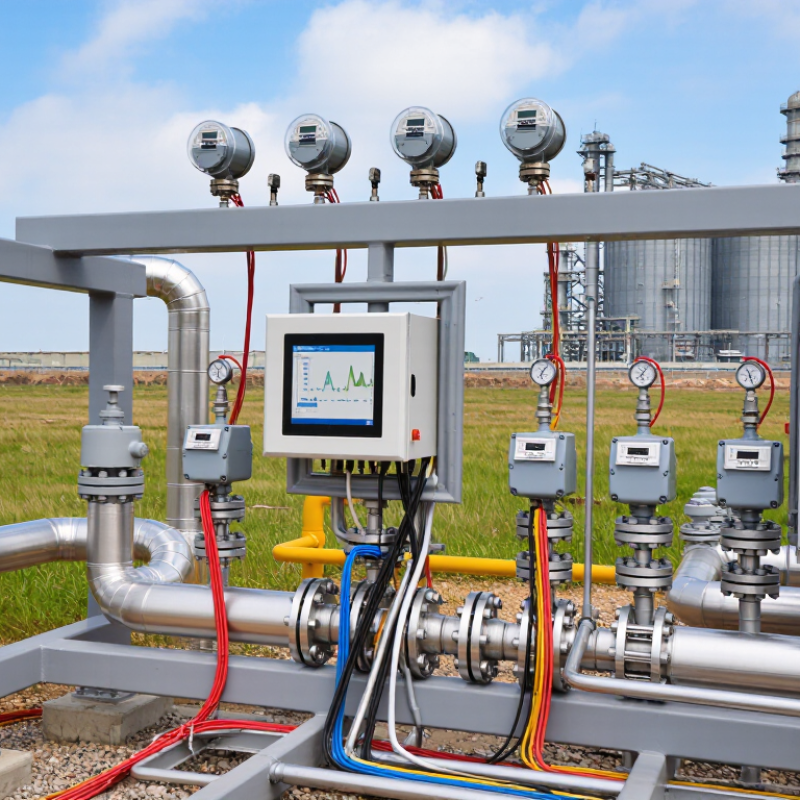
How to Integrate Metering Skids with Digital Systems?

Understanding Metering Skids and Their Digital Interfaces

How to Integrate Metering Skids with Digital Systems?

Understanding Metering Skids and Their Digital Interfaces

A metering skid brings instruments, valves, and piping together to measure fluid flow in a compact assembly. Its digital interface carries readings and status signals to a control system or data platform. Flowmeters may report flow rate and total volume, while pressure and temperature sensors provide useful operating context. These signals need clear tags, consistent units, and reliable timestamps.

Small details matter.

Before connecting equipment, engineers should check signal types, communication protocols, and the skid’s input and output list. A mismatch can leave a live reading unavailable or make an alarm appear unclear. For example, operators should be able to distinguish a low-flow warning from a sensor fault.

Test each point during commissioning, including alarms, units, and data updates under normal operating conditions. Good documentation helps later troubleshooting.

Still, a neat interface does not guarantee accurate measurement; calibration and installation conditions matter too.

This part is easy to overlook.

Teams should review data trends after startup and question readings that seem unusually steady or inconsistent.

Assessing Instrumentation, Controls, and Data Requirements

A metering skid’s digital integration starts with trustworthy measurements. Identify each flow, pressure, and temperature instrument, then confirm its range, accuracy, output, and calibration status. A meter sized for normal flow may perform poorly during low-rate operation. Check the expected turndown before selecting its signal interface, such as a pulse output or digital communication. Small details matter. Record tag names, engineering units, and signal scaling in one instrument list; mismatches can make correct readings look wrong in the control room.

The control system should define how operators view readings, acknowledge alarms, and respond to communication failures. Set practical alarm limits using process conditions, not simply the instrument’s full scale. Specify update rates, timestamps, data retention, and which values must reach the historian. For example, an operator investigating a brief flow deviation needs synchronized flow and pressure trends, not two screens with different time bases. Test the full path from sensor terminals to displayed values, including loss and recovery of a signal. A tidy dashboard can still hide poor data quality. I have seen integration plans treat tag mapping as an afterthought; it is easy to overlook, and costly to correct once commissioning is underway. Decide who owns each data point and how changes will be documented.

Designing Connections Between Skid Equipment and Plant Systems

A metering skid should connect to plant systems through a defined interface, not a last-minute bundle of cables. Document every signal: flow rate, pressure, temperature, totalizer, alarm state, and engineering unit. Agree on tag names, scaling, update rates, timestamps, and what happens when communication drops. Keep it practical. A clear interface control document helps skid suppliers and plant engineers test the same values before commissioning.

Deloitte’s 2025 Smart Manufacturing Survey, based on 600 executives, found that 92% expect smart manufacturing to drive competitiveness over the next three years. That expectation makes reliable data links more important, but connectivity alone does not create useful information. Use a plant-approved protocol, such as OPC UA or Modbus TCP, and place a managed gateway between skid controls and the plant network. Restrict write access where operators only need monitoring. Verify data against local instruments during factory and site acceptance tests. Check units carefully; a flow total reported in gallons instead of cubic metres can quietly distort a batch record. In practice, teams still miss timestamp alignment. It is easy to overlook. Review cybersecurity zones and recovery behavior with operations staff, too. Even a well-designed interface can feel clumsy when alarms arrive late.

Configuring Data Exchange, Monitoring, and Security

Integrating a metering skid means making each measurement traceable, not merely visible. Map flow, pressure, temperature, and pulse counts to consistent tag names, units, and timestamps. A gateway can translate skid signals into OPC UA or Modbus data for the plant historian. Buffer readings locally during network interruptions; otherwise, gaps can distort batch records. Test the full path with a calibrated meter and compare readings at the skid and control-room display. Small mismatches matter.

Security belongs in the data design. Separate skid controls from business networks, allow only required data paths, and use individual accounts with limited permissions. Keep remote access disabled unless needed, then log and review each session. The World Economic Forum’s Global Cybersecurity Outlook 2024 reported that 29% of surveyed organizations had experienced a material cyber incident in the previous year. The 2024 Data Breach Investigations Report found a human element in 68% of breaches it analyzed. These are broad findings, not metering-skid-specific rates, but they support careful access control and operator training. Keep it practical. One awkward truth: a polished dashboard can still show bad data if clocks drift or sensor units are misconfigured. Schedule checks, document changes, and investigate unexplained spikes before trusting automated alerts.

How to Integrate Metering Skids with Digital Systems? - Configuring Data Exchange, Monitoring, and Security

Integration Area Data or Function Typical Interface Example Configuration Monitoring and Security Considerations
Flow measurement Instantaneous flow rate, totalized volume, meter status, and diagnostic flags Modbus TCP or a hardwired 4–20 mA signal with HART where supported Flow rate in m³/h; total volume in m³; engineering units and scaling documented in the register or signal list Check values against operating limits; detect bad-quality, frozen, or out-of-range readings
Pressure and temperature Line pressure, fluid temperature, and instrument condition 4–20 mA, HART, or Modbus TCP Pressure in kPa or bar; temperature in °C; ranges matched to the installed transmitters Use configured alarm limits and sensor-fault diagnostics; retain units and measurement ranges with each tag
Skid controller to plant control system Process values, operating states, alarms, permissives, and selected commands Modbus TCP or OPC UA, subject to the approved site architecture Publish a documented tag list with data types, scaling, read/write permissions, and update behavior Separate monitoring points from control commands; validate command interlocks and test communications-loss behavior
Historian and reporting Time-stamped measurements, totals, alarm events, and quality indicators OPC UA or an approved historian interface Record critical process values at a configured interval, for example every 1–5 seconds, and log events on change Synchronize clocks with the site time service; monitor missing data, time gaps, and unexpected value changes
Data quality and communications Connection state, stale-data indication, device status, and communication errors Controller diagnostics and protocol status points Set a stale-data threshold based on the configured update interval and process response requirements Raise an alarm when updates stop; define safe operating behavior for communication loss with the responsible control engineer
Network segmentation Traffic between skid equipment and plant systems Managed industrial Ethernet with routed or firewall-controlled connections Allow only required source and destination addresses, services, and ports Keep control and business networks separated; disable unused services and review access rules periodically
Authentication and encryption User access, engineering access, and supported encrypted data exchange Role-based accounts; secure protocol options where supported and approved Use individual accounts, least-privilege roles, and unique credentials; protect configuration backups Apply site password and certificate policies; record configuration changes and remove access when no longer needed
Commissioning and maintenance Tag mapping, scaling, alarms, backups, and interface verification Approved test plan and controlled configuration records Verify representative live values, units, alarm states, timestamps, and recovery after a communications interruption Document tested settings and restore procedures; schedule updates and maintenance through the site's change-control process

Example integration considerations only. Confirm protocol support, measurement ranges, update rates, alarm limits, and cybersecurity requirements against the installed equipment and site standards.

Testing Integration and Maintaining Reliable Operations

Integration testing should begin with the signal path, not the dashboard. Confirm that each flow, pressure, and temperature value reaches the control system with the correct tag, unit, and timestamp. A reading of 12.4 may look reasonable, yet represent the wrong unit. Test normal operation and realistic edge cases, including a stopped meter and a lost communication link. Watch what operators actually see.

Use simulated inputs where practical, then compare live readings against local instruments during commissioning. Check alarm limits, event timestamps, and whether data returns cleanly after a network interruption. One useful test is to disconnect the link briefly and confirm that the skid records the gap instead of displaying stale values as current. Small discrepancies matter. Document the expected response, observed result, and corrective action for each test. The record helps teams distinguish a sensor problem from a mapping or communications fault later.

Reliable operation depends on routine checks after handover. Review trend data for unexplained jumps, flat lines, and gradual drift. Verify calibration intervals against service conditions, not just a convenient calendar cycle. Keep configuration changes controlled, with backups and clear revision notes. This is easy to neglect during busy shifts. It can also leave staff unsure which settings are active. Periodically test alarms and recovery procedures with operators present, and update instructions when the real workflow differs from the written one. A tidy interface is not proof of a sound integration.

Metering Skid Digital Integration Test Results

Illustrative acceptance-test pass rates across key integration checks. Testing should verify measurement data, timestamps, alarms, historian records, and recovery after communication interruptions before routine operation.

FAQS

What does a metering skid’s digital interface do?

It sends flow, pressure, and temperature readings to a control system. Clear tags, units, and timestamps help operators interpret each value. Small details matter.

What should teams check before connecting a skid?

Confirm signal types, communication protocols, and the input and output list. A mismatch can hide a live reading or make an alarm unclear.

How should instruments and data points be documented?

Record tag names, units, signal scaling, ranges, and calibration status in one instrument list. Assign an owner to each data point and document later changes.

How can teams set useful alarm limits?

Base limits on actual process conditions, not just an instrument’s full scale. Operators should be able to tell low flow from a sensor fault.

What should integration testing include?

Test each value from the sensor terminals to the displayed screen. Check tags, units, timestamps, alarms, and realistic cases such as a stopped meter. Test the full path.

How can teams detect stale or misleading readings?

Briefly interrupt the communication link and check how the system reports the gap. It should not present an old value as current. This is easy to miss.

What should operators review after startup?

Compare live readings with local instruments, then review trends for jumps, flat lines, or gradual drift. A tidy dashboard can still hide poor data.

How can teams keep the integration reliable over time?

Check calibration intervals against service conditions. Back up configurations, record revisions, and periodically test alarms with operators present. We sometimes overlook busy-shift changes.

Conclusion

Integrating a metering skid with digital systems starts with understanding the skid’s instruments, control functions, and available communication interfaces. Before connecting equipment, define what information the plant needs, such as flow measurements, operating status, alarms, and diagnostic data. Confirm that sensors, controllers, and data formats are suitable for the intended use, and plan how signals will connect to plant control and monitoring systems.

How to integrate metering skids with digital monitoring systems? Design reliable connections, configure clear and consistent data exchange, and apply appropriate access controls and network security measures. Test communications, measurement values, alarms, and failure responses before routine operation. Document the configuration and establish regular checks for instruments, connections, and software settings. A carefully planned integration helps operators monitor performance, identify issues promptly, and maintain dependable metering operations over time.

Ethan

Ethan

Ethan is a seasoned marketing professional with a deep expertise in our company's innovative product line. With a passion for sharing knowledge and insights, he takes the lead in regularly updating our corporate blog, where he explores industry trends, product features, and effective marketing......